CHIANYOU / SELECT THE FINISH BEFORE READING THE LIMIT
A finish-dependent process sheet, rather than one universal minimum.
Chianyou’s detailed fabrication table distinguishes tin boards at 0.15 / 0.15 mm trace / space from gold boards at 0.125 / 0.125 mm. Hole compensation and default plated-wall copper also depend on the stated route. For a buyer comparing a dense connector board with a tin-finished control board, those qualifications are more useful than a single smallest number.
Tin-board route
Trace / space
0.15 / 0.15 mm.
Tin thickness
Hole: 5 µm; SMT surface: 5–12 µm.
Default hole-wall copper
15 µm for the row’s gold-finger-board case; 20 µm for its non-gold-finger case, when no special requirement is given.
10 µm in the separately labelled nickel-gold row, when no special requirement is given.
The source does not identify every gold finish as ENIG, nor specify lead-free status for every tin route. Specify the finish process, deposit measurement and acceptance requirement on the order. These published defaults are not an IPC class declaration and are not automatically sufficient for your reliability requirement.
Selectable 1–8-layer process service
The detailed table gives 1–8 layers and a maximum processing area of 520 × 622 mm. Its minimum thicknesses are 0.4 mm at two layers, 0.8 mm at four and 1.0 mm at six; maximum thickness is 3.0 mm. It does not give a minimum eight-layer thickness. The introduction’s broader 1–20-layer wording and the lead-time table’s 8 / 10-layer entry require a separate engineering acceptance.
A 1–20-layer introduction, a 1–8-layer detailed process table and a delivery schedule mentioning ten layers are not one confirmed twenty-layer construction at all the smallest limits. The processing-area maximum is not necessarily the usable board envelope after rails and tooling.
ORIGINAL CATALOGUE / THE NUMBER IN THE TITLE IS NOT A LAYER COUNT
Compare the board families, then supply your own controlled construction.
The official catalogue separates multilayer, single / double-sided and special boards. Its 27 individual listings primarily identify pictures and category names. Below are five different corresponding originals, selected for different mechanical and fabrication questions; no dimensions are estimated from the images.
Corresponding original manufacturer catalogue image, shown whole. Its catalogue number and appearance do not establish engineering specifications.
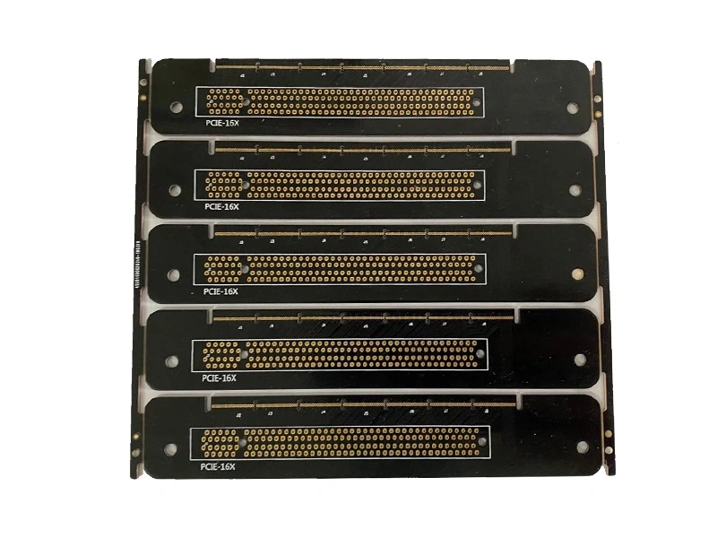
Multilayer catalogue No. 8 — black connector panel
Source context
Manufacturer multilayer category, catalogue title 多层线路板8. The number 8 is a catalogue label, not an eight-layer specification.
Finished hole / impedance
Not specified for this reference
Material / thickness / copper
Order-specific drawing and controlled material selection
Provide the actual stack, connector finished-hole fits, pad finish, contact wear requirements and panel datums. Mask colour does not identify the laminate or impedance performance.
Corresponding original manufacturer catalogue image, shown whole. Its catalogue number and appearance do not establish engineering specifications.
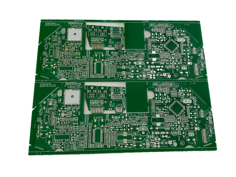
Multilayer catalogue No. 3 — green two-up panel
Source context
Manufacturer multilayer category, catalogue title 多层线路板3; no exact stack or dimensions published.
Finished hole / impedance
Not specified for this reference
Material / thickness / copper
Order-specific drawing and controlled material selection
Release the stack, layer registration targets, copper, rail and breakaway drawing. Ask for the actual drill and netlist-test route instead of assigning general limits to the picture.
Corresponding original manufacturer catalogue image, shown whole. Its catalogue number and appearance do not establish engineering specifications.
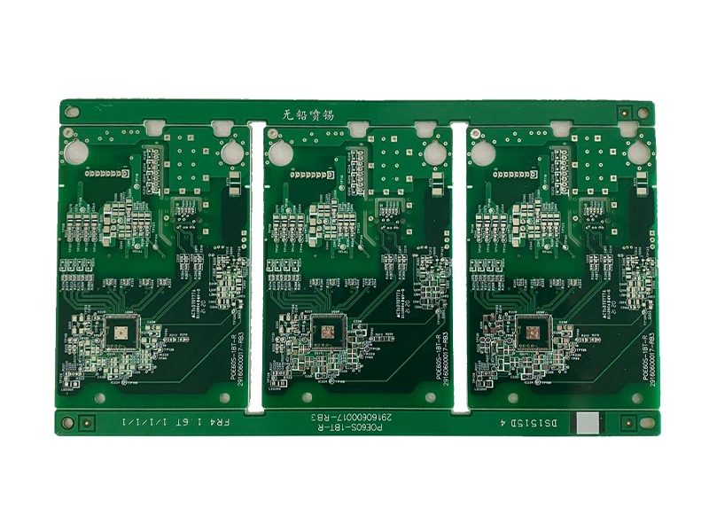
Single / double-sided catalogue No. 4 — green panel
Source context
Single / double-sided family, catalogue title 单双面线路板4. The individual example does not specify which of the two constructions applies.
Finished hole / impedance
Not specified for this reference
Material / thickness / copper
Order-specific drawing and controlled material selection
Confirm one- or two-sided construction, plated and non-plated holes, board thickness, laminate grade and connector fits from the fabrication drawing.
Corresponding original manufacturer catalogue image, shown whole. Its catalogue number and appearance do not establish engineering specifications.
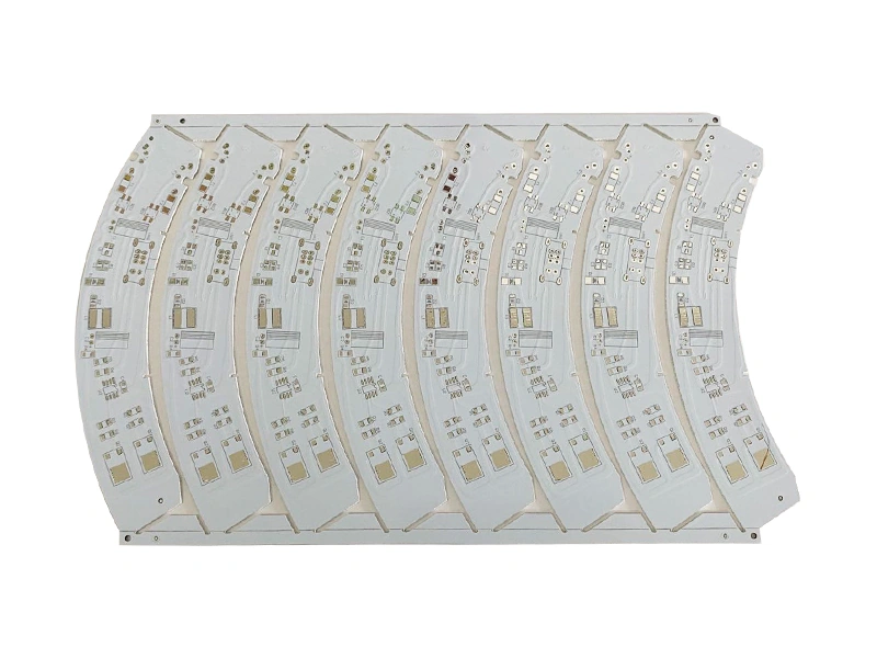
Special-board catalogue No. 3 — curved white reference
Source context
Manufacturer special-board category, catalogue title 特种线路板3. Neither metal base, dielectric nor a thermal rating is disclosed for this image.
Finished hole / impedance
Not specified for this reference
Material / thickness / copper
Order-specific drawing and controlled material selection
For a thermal design, name the required base, dielectric thickness, thermal data and insulation test. Separately define curve datums, tooling and finish; do not infer aluminium from the white surface.
Corresponding original manufacturer catalogue image, shown whole. Its catalogue number and appearance do not establish engineering specifications.
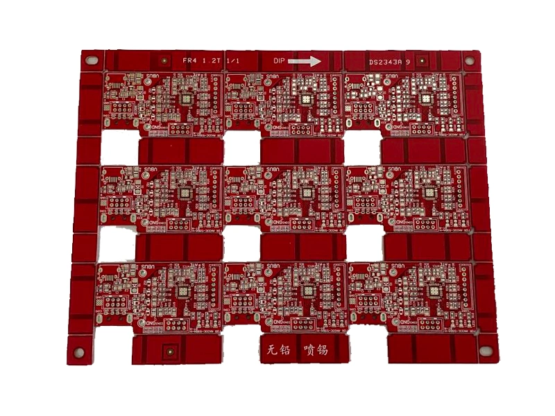
Special-board catalogue No. 6 — red panel reference
Source context
Manufacturer special-board category, catalogue title 特种线路板6; material, layer stack and application not specified.
Finished hole / impedance
Not specified for this reference
Material / thickness / copper
Order-specific drawing and controlled material selection
Specify the intended application, exact substrate and stack, outline, solder-mask and legend acceptance. Ask what makes the requested construction special before comparing its price with ordinary FR-4.
“Multilayer board 8” is a catalogue title, not an eight-layer specification. “Single / double-sided board 4” does not establish four layers. The special-board label does not, by itself, establish aluminium base, RF laminate, flex or HDI. Repeated photos within the catalogue are not counted as new physical designs.
A 0.30 mm drill minimum is not a 0.30 mm finished-hole promise.
The process sheet expressly names minimum drilling at 0.30 mm. It separately gives NPTH tolerance ±0.05 mm and PTH tolerance ±0.08 mm, without publishing a minimum plated finished-hole diameter. A pin or press-fit requirement must be stated as a finished-hole callout with an agreed measurement method.
Tin-board compensation
The table lists PTH drill compensation of 0.15 mm for 1 oz and 0.20 mm for 2 oz. Ask CAM how that allowance is applied to your finished-hole nominal and plating requirement; it is not the accepted finished-hole size.
Gold-board compensation
The separately labelled plated-gold route lists 0.10 mm for 1 oz and 0.15 mm for 2 oz. The NPTH allowance is separately listed as 0.05 mm. Do not exchange these route-specific allowances when comparing quotations.
Hole-to-hole web
Minimum hole-edge to hole-edge separation: 0.2 mm. Confirm the actual finished geometry and process route.
NPTH near the outline
Hole edge to routed edge ≥0.3 mm; to punched edge ≥0.5 mm. NPTH edge to circuit ≥0.3 mm.
Locating holes
If a customer leaves board-edge locating holes unspecified, the source says it uses a 2.0 mm finished hole. Explicitly define your assembly-tooling holes rather than relying on that default.
Connector pads
The source gives one-side component-hole pad allowance greater than 0.15 mm and via-pad allowance greater than 0.12 mm. These are not an independent measured annular-ring result for the pictured connector panel.
OUTLINE AND ARTWORK / CLARIFY THE DRAWING BEFORE CAM RELEASE
Scored and routed panels have different edge rules.
Routing and punching
The published perimeter values are CNC routing 0.13 mm, hand routing 0.2 mm and punching 0.1 mm. The row does not print a ± sign; obtain the tolerance definition and datums instead of adding one. The smallest routing tool is 0.8 mm.
Inner copper to edge is 0.5 mm one-sided. Outer circuit to routed edge is 0.2 mm, versus 0.40 mm for a punched edge. The router-centre-to-copper row separately gives a 0.2 mm one-side minimum; have CAM mark up the controlling geometry.
V-scoring
Unless otherwise specified, residual thickness is one third of board thickness, controlled to ±0.1 mm; score deviation is stated as ±0.10 mm. Define the residual web for the assembly’s handling and separation requirements.
One row says circuit-to-V-cut ≥0.4 mm for boards at least 1.0 mm thick, while the final scoring row requires a 0.5 mm one-side minimum to circuit and copper. Ask which rule controls your drawing; the less restrictive value is not a safe automatic filter.
Mask dams and openings
The sheet lists 0.25 mm SMT pad spacing for retaining a mask bridge and a 0.1 mm minimum bridge. Opening allowances are separately given for photosensitive mask, screen printing and gold fingers. Send the actual pad geometry and ask for an agreed mask artwork rather than adding these values together.
Legend needs clarification
The source prints character height 0.07 mm alongside 0.12 mm stroke and 0.15 mm outline stroke. That height is inconsistent with the listed stroke; it is retained as a source discrepancy, not silently corrected. Agree a legible character height and the >0.1 mm clearance from mask pads.
Trace / space error is stated as ±20% and circuit alignment deviation as 0.10 mm. Neither is an impedance tolerance. For controlled impedance, provide the stack, target structures, coupon method and report requirement; the reviewed process sheet does not publish an impedance percentage.
FABRICATION AND MEASUREMENT / LINK THE ASSET TO YOUR ACCEPTANCE
The inventory helps ask about the actual production route.
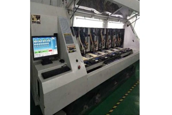
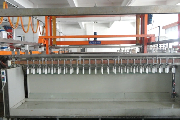
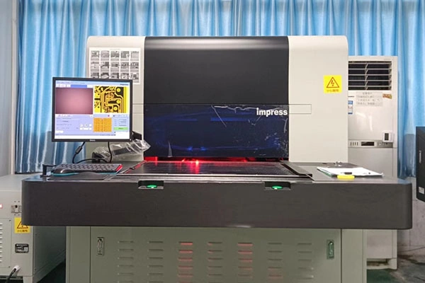
Original production-gallery drilling-line photograph. The gallery is not a dated installed-asset audit.Original wet-process-line photograph; the same line image appears twice in the source gallery.Original imaging-machine photograph, marked Impress. It does not establish a model-specific minimum feature.
Published equipment counts
The undated table lists 16 CNC drills, two automatic PTH lines, one panel-plating line, eight CNC routers, three punches, three V-cut machines, four AOI scanners and one vacuum etcher. It also lists three exposure machines, four automatic screen printers, eight ovens, one OSP machine and one vacuum packer.
The heading says “current quantity,” but no observation date or asset schedule is supplied. Ask which machines and site will process the released revision. A count does not establish available capacity or calibration status.
Marketing and inventory are separate
The website’s promotional text mentions automatic LDI and a German flying-probe machine. Those items are not separately named in the typed equipment inventory, and the photos are not mapped to a current serial-number register. Ask for the current imaging and electrical-test route; no laser-drill or HDI qualification is inferred.
The published flow illustrates cutting, drilling, PTH, plating, imaging, etching, mask, legend, tin finishing, outline, testing and packing. It does not show inner-layer lay-up and lamination, so it is not a complete multilayer traveller.
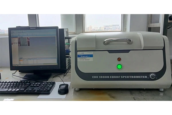
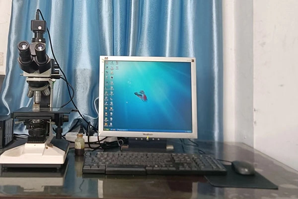
Original gallery EDX1800B instrument photograph. A visible instrument label is not a coating-thickness result for an order.Original microscope-bench photograph; request the cross-section plan and recorded measurements for the released stack.
Request the output, not just a machine photo
The measurement list includes microscopes, metallographic sectioning, a two-dimensional measuring instrument, pin gauges, residual-thickness gauge, caliper, micrometer, balance and copper-foil thickness tester. All quantity cells in that list are blank.
For a connector board, agree finished-hole gauging and the plating cross-section. For scoring, agree residual-web measurements. For gold contacts, agree deposit measurement, sampling and the report attached to the shipment. AOI and dimensional inspection do not replace the order’s electrical test.
PUBLISHED DAYS / FIRST ORDER, FORECAST REPEAT AND CLARIFIED SAMPLE
Choose the order condition before comparing lead times.
The official delivery table uses three English headings: First Order, Repeat Order With Forecast, and Sample after clarification of design issues. Its Chinese labels differ in meaning under the first two columns. The values below follow the English headings without pretending that the discrepancy has been resolved.
Aluminium-base route
First order
5–7 days
Forecast repeat
4–6 days
Clarified-design sample
2–4 days
Double-sided
First order
7–10 days
Forecast repeat
5–7 days
Clarified-design sample
3–5 days
Four / six layers
First order
14–16 days
Forecast repeat
10–12 days
Clarified-design sample
7–10 days
Eight / ten layers
First order
18–20 days
Forecast repeat
14–16 days
Clarified-design sample
8–10 days
These are manufacturer-published production periods, not a current quotation, stock allocation or shipping promise. The table does not say calendar versus working days. Confirm file approval, materials, quantity, holidays and dispatch. The homepage’s 12-hour prototype promotion should not replace the route-specific schedule.
The aluminium-base entry establishes a separately named delivery route; it is not proof that the white curved catalogue board has an aluminium base. The eight / ten-layer timing entry likewise does not expand the detailed 1–8-layer process table without a current engineering decision.
BOLUO PRODUCTION ADDRESS / THREE CONTACT ENTITIES
Name the producing company and contracting party separately.
Original website company photograph with Chianyou branding; no factory-floor area is inferred from the picture.
Huizhou identity
The website names 千友(惠州)电子有限公司, Chianyou (Huizhou) Electronics Co., Ltd. Its contact address is 4/F, Building 1, Dongrun Industrial Centre, north of Yuanjiao Road, Shiwan, Boluo, Huizhou, Guangdong.
The contact page also names Hong Kong 金阳实业有限公司 and Dongguan 东莞市千广电子科技有限公司. It does not establish three separately audited factories. Confirm the seller, invoice issuer, producing site and responsibility for any subcontracted operation on the purchase order.
The introduction states founding in 2011 and an experienced manufacturing team. Its undated claims of 100+ employees, 8,000 m² premises, 25,000 m² monthly output and CNY150 million annual output are not current available capacity. The homepage’s 5,000+ m² workshop wording has a different scope and is not added to the premises figure.
Commercial engineering handoff
The published sales contact is Zhang Shaoshen (张绍深), deputy general manager for business, at zsshen@chianyou.com. General manager Liao Xinxi (廖新喜) is listed at l.x.x@chianyou.com.
Production clarification
The published production contact is Ma Yuan (马圆), deputy general manager for production, at mayuan@chianyou.com. These are official-site disclosures; mailbox control has not been tested and no message has been sent during this review.
HISTORICAL RECORDS / HOLDER, DATE AND CONSTRUCTION ARE DIFFERENT CHECKS
Use dated documents for the questions they actually answer.
The Guangdong Department of Science and Technology’s original 2023 third-batch high-tech-enterprise list names 千友(惠州)电子有限公司 at row 3888, PDF page 101, certificate reference GR202344013056, Huizhou. That historical entity-recognition entry does not qualify a PCB construction or establish current available production.
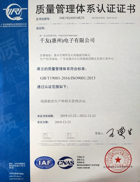
ISO 9001 — displayed Chinese copy, expired 2022Original ISO 9001:2015 copy: 04819Q40856R2S, 千友(惠州)电子有限公司, validity 23 December 2019–22 December 2022.
The scope covers circuit-board production and related management activities. The website’s English copy shows an earlier 2016–2019 period. Neither copy is a current issuer confirmation.
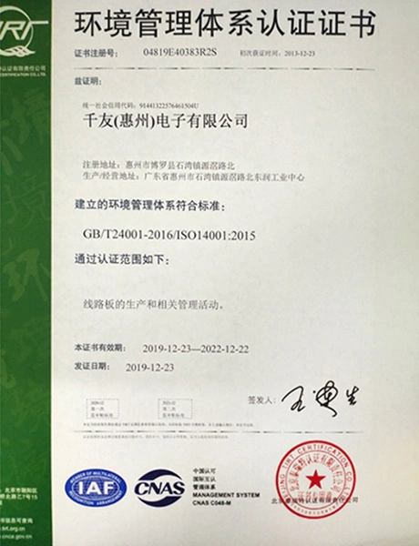
ISO 14001 — displayed Chinese copy, expired 2022Original ISO 14001:2015 copy: 04819E40383R2S, same company, validity 23 December 2019–22 December 2022.
This is a dated environmental-management-system document, not a PCB quality or product approval. A current certificate should include the relevant legal holder, production address and scope.
UL — historical correspondence, not a current construction annexOriginal UL letter dated 20 October 2016, addressed to CHIAN YOU (HUIZHOU) ELECTRONICS CO LTD; file E412804.
The letter concerns procedure / report material and revised index / report pages. It does not reproduce the complete construction annex or a current Product iQ holder record. Confirm the recognised construction, site and permitted marking for the exact laminate / stack rather than applying this file to all catalogue boards.
The introduction’s additional TS16949, CQC, military-system and discharge-permit claims are not converted into current badges. Customer names and application images are also not endorsements. Ask for the specific current issuer or regulator record where the order requires it.
QUOTE PACKAGE / REMOVE THE PROCESS AMBIGUITIES BEFORE PRICING
Give the factory a construction it can explicitly accept.
Entity and route: contracting party, Huizhou producing site, finish and any outsourced operations.
Stack and materials: actual layer count, laminate grade, finished thickness, copper, material trace and the combined trace / space requirement.
Holes and contacts: finished PTH / NPTH callouts, tolerance, compensation decision, plating thickness, deposit measurements and connector acceptance.
Panel and artwork: usable panel size, outline datums, routing or scoring, residual web, copper clearances, mask dams and legible legend.
Release and delivery: controlled revision, current production and test route, inspection reports, qualification scope and the event starting the agreed lead time.
Reviewed 9 October 2026. Five original catalogue references and one separately scoped process service are selectable. The photographed boards’ unreported parameters remain unknown; general process values stay attached to their route.
Forty manufacturer pages, corresponding original images and the government original were read separately. Catalogue numbering, special-board labels and historical documents are kept within their actual scope.