
In this guide
A capability table can be accurate in every cell and still lead you to the wrong factory shortlist. The trap is treating the largest layer count, finest track, smallest hole and tightest impedance tolerance as a single manufacturable combination.
Those values may come from different products, copper weights, stackups or processes. A filter can find reported numbers that meet your thresholds. It cannot establish that all those numbers work together on your board. That distinction matters before you share files, compare quotations or promise a delivery date.
The combination that the table does not prove
Consider an illustrative requirement: six layers, 2.5 mil trace and space, and ±5% controlled impedance. A supplier profile reports a layer range containing six, a minimum trace at or below 2.5 mil, and an impedance figure at or below ±5%. The profile passes those individual comparisons.
Now ask what is missing. Does the fine-line figure apply to the intended outer-layer copper? Is the spacing figure the same as the trace figure? Does the impedance statement apply to your target impedance, geometry and stackup? Is the tolerance a standard production commitment or an advanced option requiring engineering approval?
This example is hypothetical. It does not establish that any particular factory can or cannot build the board. It shows why a numeric match should produce a candidate for review rather than a manufacturing approval.
Copper weight changes the question
A minimum line or space value is incomplete without its copper conditions. Eurocircuits' manufacturing guidance explains that copper thickness affects the minimum track and isolation dimensions. Its guidance also distinguishes inner- and outer-layer features and the effects of imaging and etching.
For your own RFQ, state the copper requirement for each layer and distinguish starting copper from the finished requirement where relevant. Ask the manufacturer to return the supported trace and spacing values for those conditions. Do not copy a headline fine-line number into a heavy-copper design rule without checking its applicability.
The action here is simple: keep trace and space as separate fields, include units, and ask which layers and copper conditions each limit describes. If the source publishes only one of the two values, leave the other unresolved. Filling an empty spacing field with the trace value creates information that the source never supplied.
A hole dimension needs a definition
When a table says “minimum hole,” determine whether it refers to a mechanical drill tool, a plated finished hole, a non-plated hole or a laser microvia. These are different requirements. The board thickness and the depth being drilled also matter when discussing aspect ratio and the available process route.
Write the finished hole requirement, tolerance and hole type into your fabrication package. Ask the supplier which drill and plating assumptions it will use. For blind or buried structures, ask for the proposed layer spans and build sequence rather than assuming that the smallest published hole can be applied across the complete board thickness.
A useful supplier answer connects the value to the process. An answer that merely repeats the original capability table leaves the uncertainty unchanged.
Impedance is a controlled requirement, not just a percentage
A ±5% entry has little meaning until both sides agree what is being controlled. Define the target impedance and whether the structure is single-ended or differential. Identify the relevant layers, stackup assumptions, material and geometry, then agree how compliance will be assessed and reported.
Ask who proposes and approves any trace-width or stackup adjustments. A quote that depends on changing a controlled feature should say so before fabrication. The purpose of this discussion is to create an agreed specification, not to infer precision from the presence of a test-instrument name in an equipment list.
A TDR-related equipment statement can support a question about testing. It does not by itself prove a particular impedance outcome for your design or establish the acceptance criteria you intend to use.
Turn the matrix into an engineering brief
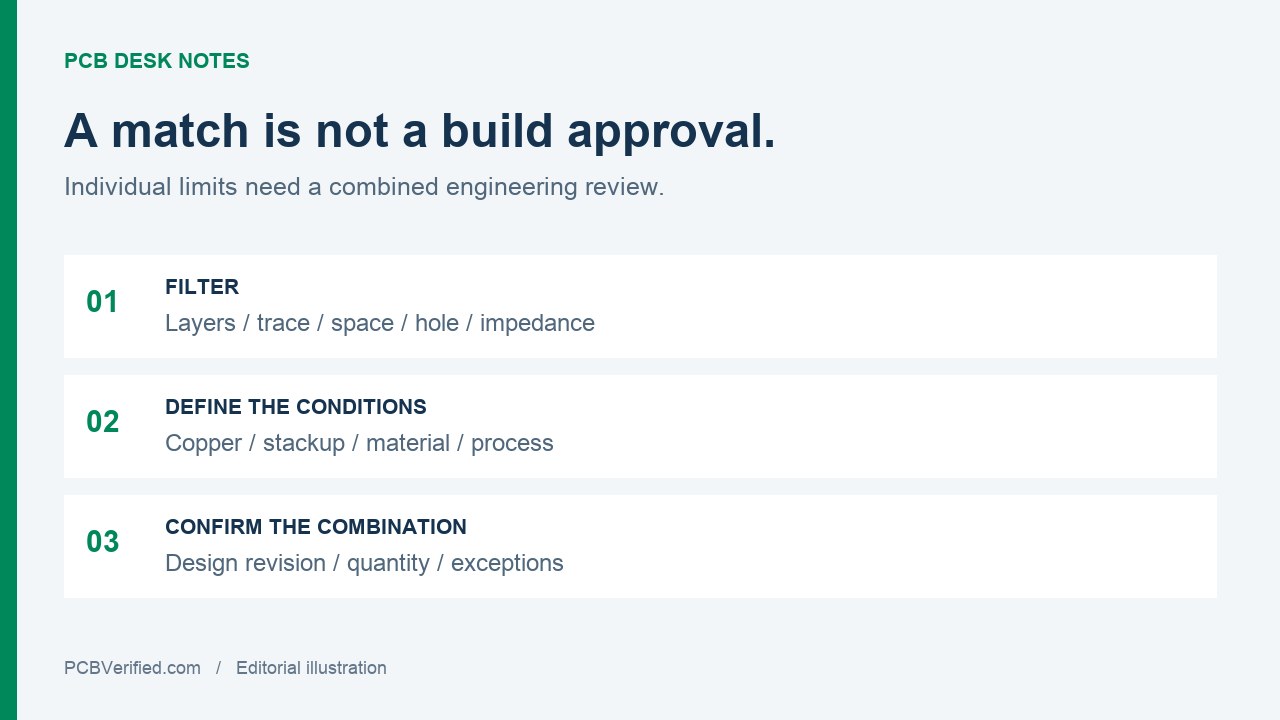
First, filter with requirements you can actually define. Set layer count, trace and space, hole requirement and the relevant technology. Preserve unknowns. A profile without a reported value is not a confirmed pass, but it may still merit a targeted enquiry if other evidence is relevant.
Second, shortlist the candidates and send one controlled revision to each. Include the drawing, stackup requirements, copper information, controlled features, quantity and requested delivery conditions. State which features must not change and which alternatives you are willing to review.
Third, require a response against the combination. Ask the supplier to name the manufacturing site, identify external process steps, list exceptions and return its proposed stackup or manufacturing assumptions. If a supplier requests a relaxation, compare that revised offer separately instead of treating it as an equivalent quote.
Fourth, keep the confirmation with the quotation. Record the revision and date, the proposed process and the approver on each side. When the design or the order conditions change, revisit that confirmation instead of assuming the previous answer still covers the job.
Copy this question into your RFQ
“Please confirm whether this exact combination can be manufactured at the named facility for the attached revision and quantity. Identify the applicable trace and spacing limits by layer and copper condition, the finished hole requirements, the proposed stackup and controlled-impedance acceptance method. List any substitutions, subcontracted processes, exceptions or design changes before quoting.”
Follow that with the actual design values. Do not leave the supplier to reconstruct critical requirements from a short email subject or a screenshot. The quality of the response is easier to assess when the question is specific and the same brief goes to every shortlisted supplier.
What the PCBVerified match means
Our matrix is a screening tool built from recorded capability and evidence fields. An individual threshold match is not independent confirmation of the complete build. The combination still needs a factory response tied to your design.
The honest outcome is a smaller, better-informed shortlist with its remaining questions visible. Use the evidence status beside each profile, read the source context, and obtain the manufacturing confirmation before treating a candidate as approved. A capability table is most useful when you know exactly what it has not yet established.
Sources & editorial scope
Eurocircuits: track and isolation tolerances ↗
Eurocircuits: pattern and drill classification ↗
Reference publisher: eurocircuits.com. Original reference retained in the editorial record.
This guide is published by PCBVerified. Confirm design-specific requirements and supporting evidence against the applicable manufacturing profile.
How PCBVerified records evidence →