Choose the material route before asking for a quick turn.
Lianchuang's published examples span three quite different procurement decisions: an RF material or machined cavity, a metal base for a thermal assembly, and a dense or flexible interconnect. The manufacturer describes a prototype and small-batch business founded in 2007. Its Chinese legal name is 深圳市联创电路有限公司; the homepage uses Shenzhen Lianchuang Circuit Co., Ltd., while its English logo reads Shenzhen Lianchuang Electronics Co., Ltd. Match the Chinese entity on the contract.
Do not start with the site's shortest delivery headline. First identify the exact laminate, stack, processing route and quantity. Its detailed process sheet distinguishes samples of ≤3 m² from small/mid-sized batches of ≤20 m², and the displayed sheet is dated February 2019. That distinction makes the page useful for preparing questions, while a current engineering approval is still needed for the order.
Three RF examples, three different fabrication briefs.
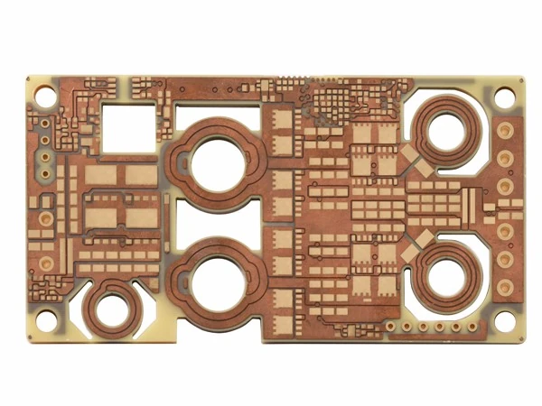
Four-layer Rogers + blind slot: the original specimen associated with this catalogue title.
Four-layer Rogers with blind slots
The detail specifies Rogers material, 1.6 mm board thickness, 20/20 mil trace/space and a 0.3 mm hole field. It does not name the laminate grade or define whether that hole is a drill or finished value.
A cavity drawing should state depth, remaining dielectric, corner treatment and the datum used for inspection. Define whether metallisation is required on the cavity and what the RF acceptance actually measures. Neither slot tolerance nor insertion loss can be read from this photograph.
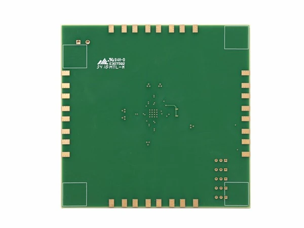
FR-4 + Rogers specimen.
FR-4 / Rogers 4003 hybrid
The example names Shengyi and Rogers 4003, 1.2 mm thickness and 4/4 mil trace/space. The title supplies no layer count; the 0.3 mm hole field has no stated process stage.
Attach a layer-by-layer material map showing the RF laminate, FR-4 cores, bonding layers and copper. Ask which laminate thicknesses are stocked and which must be purchased. The 2019 sheet says Rogers prepreg may need to be customer-supplied; resolve responsibility and lead time before accepting a schedule.
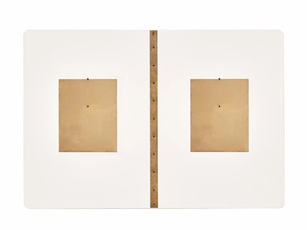
Double-sided Rogers 4350B specimen.
Double-sided Rogers 4350B
The main detail and homepage list 1.6 mm thickness and 8/8 mil routing. A recommendation card instead shows 0.8. Confirm the revision and stack thickness before quotation rather than silently treating those entries as the same board.
The hole field reads “0.5” without a unit or process definition. Specify finished holes on the drawing. For a controlled RF route, add frequency range, conductor and dielectric requirements, impedance target and the agreed coupon or test method; this catalogue supplies no product-specific impedance tolerance.
THERMAL STRUCTURE / ELECTRICAL ISOLATION
A copper base is not a heavy-copper routing specification.
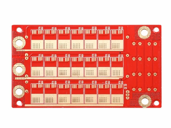
Double-sided copper-base specimen, not an assembled thermal qualification.
Double-sided copper-base PCB
The catalogue identifies copper as the base material and lists 20/20 mil routing and 0.8 mm in its hole field. Its thickness field is simply “2.0”, with no unit in the detail. These omissions need drawing-level clarification.
Keep base-metal thickness, dielectric thickness and conductor copper weight as three separate requirements. Request the dielectric grade, thermal conductivity declaration and electrical isolation test that apply to the supplied construction. Also define insulated holes, mounting surfaces, flatness and any exposed metal interface.
The older general capability table lists single-sided metal-base routes, while this product title is double-sided. Have the manufacturer identify the actual process and production location for this construction; do not apply the single-sided table's finished-hole limit to it.
REGIONAL CONSTRUCTION / SEQUENTIAL LAMINATION
Release the flexible region and HDI via map independently.
Six-layer rigid-flex catalogue specimen.
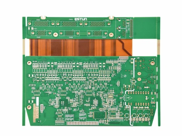
Six-layer rigid-flex
The named material is Shengyi Tg150; the table gives 1.6 mm thickness, 3/3 mil routing and a 0.2 mm hole field. It does not identify the polyimide film, coverlay, flexible-region thickness or bending duty.
A total thickness does not describe every region. Submit separate rigid and flex stacks, coverlay openings, reinforcement and bend keepouts. State whether the installed circuit bends once or repeatedly, and agree bend radius, cycles and inspection against that duty. Do not turn this specimen into a dynamic-flex qualification.
Ten-layer HDI specimen.
Ten-layer HDI
The detail names Shengyi Tg170, 1.6 mm thickness and 3/3 mil routing. Its “0.1” hole field has no unit or process stage. Ten layers alone do not identify a buildup sequence.
Provide the blind/buried via map, capture pads, stacked or staggered arrangement, fill and cap requirements, and the number of sequential laminations. Ask for the applicable microsection and reliability evidence for that route. The separate 2019 sheet allows different HDI types for samples and batches; obtain a current approval for the actual ten-layer construction.
2019.02 SHEET / CONDITIONS RETAINED
Sample and batch limits are not interchangeable.
The older table is unusually detailed about copper weight, order area, material and layer-specific constraints. These selected rows explain why the finest routing value cannot be combined with every layer count, metal base or delivery tier. They are dated manufacturer statements, not a new process approval.
Sample column: ≤3 m²
Ordinary FR-4 / high-Tg construction: 1–22 layers; ten layers and above require high-Tg material.
HDI types: 1+N+1 and 2+N+2; same-side laminations ≤4.
Inner routing on ½ oz copper: 3/3 mil; on 1 oz: 3/4 mil.
Outer ⅓ oz: 3/3 mil, with the sheet's 3 mil routing density condition ≤10% of the surface.
Ordinary FR-4 / high-Tg construction: 1–18 layers; ten layers and above require high-Tg material.
HDI type: 1+N+1; same-side laminations ≤2.
Inner routing on ½ oz copper: 4/4 mil; on 1 oz: 5/5 mil.
Outer 1 oz: 5/5.5 mil; the ½ oz row's stated density condition must also be clarified.
Impedance: ±10%; ≤5 controlled impedance groups.
Material, finished-hole and acceptance conditions
The ceramic-filled RF material row names Rogers 4000 and 3000 series: the sample column allows four-layer boards up to 3 m²; the batch column is limited to two layers. Mixed Rogers/FR-4 stacks are separately listed at ≤8 layers. These conditions are not extended to an unspecified future RF stack.
The table explicitly labels certain values as finished mechanical holes: PTFE including hybrid construction is 0.25 mm for samples and 0.3 mm for batches; ceramic-filled high-frequency material including hybrids is 0.25 mm in both columns. These values are different from the vague hole fields on the six specimens above.
The sample column cites IPC Class 3 for specified copper, thickness, outline, annular-ring and bow conditions; the batch column cites Class 2. That is a stated acceptance framework, not evidence that every catalogue item has passed a Class 3 audit. Agree the edition, drawings, exceptions and lot report in the purchase specification.
DELIVERY START / SITE SCOPE / LOT ACCEPTANCE
Agree when the fabrication clock starts and what closes the order.
A delivery tier needs a released job.
The delivery graphic shows two-layer boards at 4 days standard / 1 day fastest; 4–6 layers at 6 / 2 days; 8–10 layers at 8 / 3; 12–16 at 12 / 4; 16–20 at 14 / 5; and 20–30 at 16 / 6. Layer bands overlap at 16 and 20. Ask which band applies and whether the clock begins after engineering questions, approved stack and material availability are resolved.
The graphic's upper 30-layer band also exceeds the older process sheet's 22-layer sample maximum. It is not used as a 30-layer specification here. For production batches the graphic instead says one week for two layers, two weeks for 4–10, and two to three weeks for ten layers and above. Establish calendar/working-day definitions, quantity and shipping separately.
Specify inspection for the chosen construction.
The inspection page describes electrical testing and AOI and lists high-voltage, impedance, microsection, solderability, thermal-shock, insulation-resistance and ionic-contamination testing. Homepage equipment photographs identify PTH deposition, brown oxide and flying-probe equipment. Those are published process descriptions and images; agree which tests your lot receives and request the relevant traceable results.
Freeze the material grades, region/stack drawing, via or cavity map, copper and finish.
Obtain the current sample or batch process approval for the actual combination.
Agree the supplier entity, production site, start condition and ship date.
Define first-article and batch inspection, material lot evidence and change notification.
Individually researched 8 October 2026. Each specimen uses its named homepage image; detail galleries include other products. Dated process and delivery conditions remain separate from the specimen specifications. Units, finished-hole stage and current certificate status are not inferred.