

Compare the interfaces before comparing the quote.
The original images below belong to these named entries on CEE’s rigid-flex product page. Dimensions use the Chinese original’s millimetre values; they have not been reconstructed from the rounded English mil conversions.
A ten-layer display interconnect
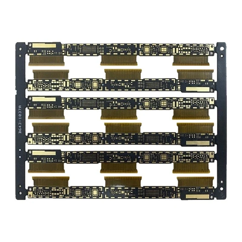
- Construction / thickness
- 10-layer rigid-flex / 0.7 mm
- Line / space
- 0.075 / 0.087 mm
- Published hole descriptions
- Blind: 0.10 mm; through: 0.15 mm
- Finish / build-up
- ENIG / two-stage HDI rigid-flex
The display connection needs a mechanical drawing as well as fabrication files. Mark connector interfaces, flex zones, stiffener boundaries and assembly clearances. Ask how the two-stage build-up crosses the rigid-to-flex transition and which dimensional checks will be supplied.
Define plated finished-hole sizes in the drawing: the catalogue does not identify its hole values as finished diameters.
Eight layers overall does not describe the flex section.
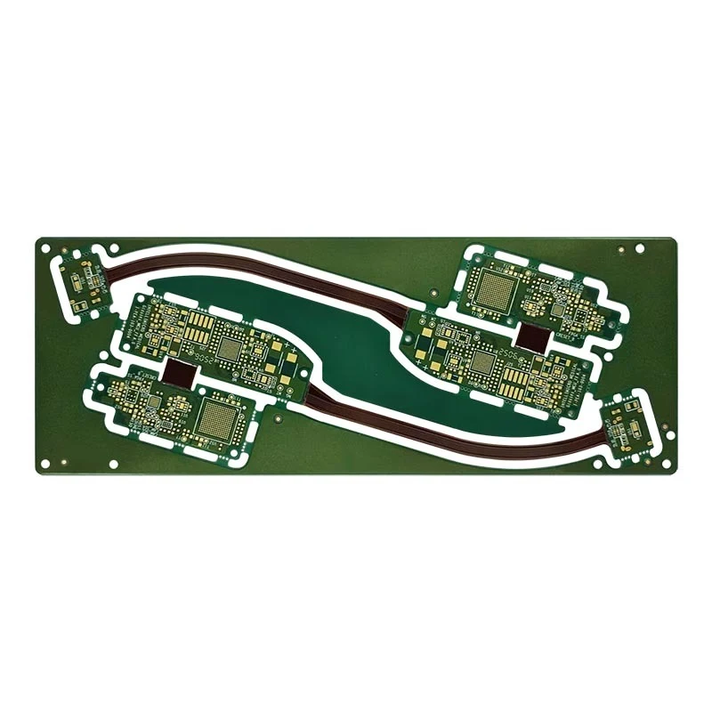
- Construction / thickness
- 8-layer rigid-flex / 0.8 mm
- Named flex section
- 4-layer FPC; two-stage HDI
- Line / space
- 0.121 / 0.063 mm
- Holes / finish
- Blind: 0.10 mm; through: 0.20 mm / ENIG
Request a section drawing that identifies the four flexible layers within the eight-layer assembly. Give the installed bend path, clearance and assembly temperature, and say whether bending occurs during installation or throughout service. The photograph supplies no bend-radius or cycle-life qualification.
Keep trace and spacing separate: this entry publishes an asymmetric 0.121 / 0.063 mm pair.
A named electrical target in the flexible region
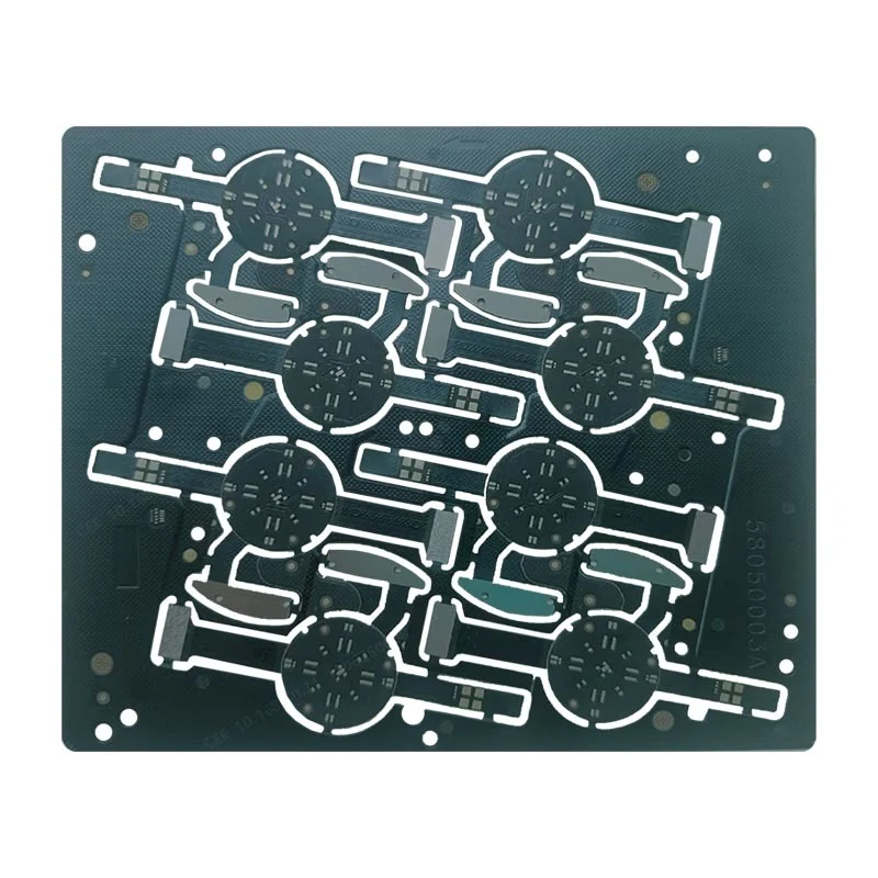
- Construction / thickness
- 6-layer rigid-flex / 0.65 mm
- Line / space
- 0.075 / 0.075 mm
- Published holes
- Blind: 0.076 mm; through: 0.15 mm
- Finish / electrical description
- ENIG; shielding/grounding; flex region 50 Ω ±10%
The 50 Ω ±10% value is attached to this watch entry. Ask for the impedance stack, reference plane, test coupon and measurement conditions for your flex region. Include coverlay, adhesive and copper requirements, then agree how the assembly’s mechanical use will be qualified.
A high-layer quote needs the correct column.
The HLC roadmap labels 2026 sample and mass-production columns separately. Its 2027 and 2028 columns describe future targets. The following excerpts apply to HLC, not automatically to the three rigid-flex examples.
Development window
- Maximum layers
- 30
- Board dimensions / thickness
- 670 × 580 mm / 0.3–4.0 mm
- Inner / outer line-space
- 50/50 μm / 65/65 μm
- Through-hole plating aspect ratio
- 20:1
- Impedance tolerance
- ±8%
Volume-production window
- Maximum layers
- 28
- Board dimensions / thickness
- 620 × 580 mm / 0.4–3.8 mm
- Inner / outer line-space
- 65/65 μm / 75/75 μm
- Through-hole plating aspect ratio
- 16:1
- Impedance tolerance
- ±10%
The Chinese original identifies dimensions and μm line/space explicitly; the English version contains mistranslated labels. Ask for the current engineering revision. These separate maximum/minimum entries are not a qualified combined stack. Back-drill stub entries also differ: 0.05–0.20 mm for sample and 0.05–0.25 mm for mass production.
Specify the responsible entity and fabrication site.
CEE’s 2026 half-year report summary identifies 惠州中京电子科技股份有限公司, Shenzhen stock code 002579, and the office at No. 1 Zhongjing Road, Chenjiang, Zhongkai High-tech District, Huizhou. Its company introduction dates the business to 2000 and lists four production bases: Huizhou Zhongkai, CEE Topsun in Zhuhai Xiangzhou, Zhuhai Fushan and Quantech in Thailand’s Rojana Ayutthaya industrial park.
The Chinese site supplies the Thailand location; the English introduction uses a conflicting geographical phrase. A purchase order should name the actual approved entity, plant and origin. Group footprint is not evidence that every product route is available at every site.
Equipment descriptions to discuss with engineering
The official production and equipment pages name Schmoll mechanical drilling, Orbotech LDI, laser drilling, vacuum lamination, plasma desmear and via-filling lines. The laser equipment entry publishes a 0.065 mm minimum blind-hole diameter; the LDI entry publishes 0.015 mm resolution and ±0.010 mm registration. These are manufacturer equipment descriptions, separate from finished-board acceptance and specific product limits.
For HDI, ask for the chosen drill/lamination sequence and via-fill cross-section criteria. For rigid-flex, ask for flex lamination and coverlay control. For FPCA, make component procurement, assembly and functional-test ownership explicit. Machine model serials, site allocation and calibration records belong in the agreed qualification package.
Make the first response actionable
- Send a construction packageRigid/flex stack, region drawing, material grades, copper, coverlay, finish and final-hole table.
- Describe the assembly useInstalled bend geometry, movement, connector/stiffener interfaces, environmental requirements and production quantities.
- Agree release evidenceNamed site, current process revision, electrical and mechanical acceptance, coupons, cross-sections, traceability and change approval.
Official sales contact: sales@ceepcb.com · +86 752 570 3333. The investor contacts in the listed-company report serve disclosure enquiries, not PCB purchasing.
Compare rigid-flex manufacturers → · Prepare a fabrication brief →
Sources behind this profile
Individually reviewed on 8 October 2026. The issuer summary cross-checks legal identity and office address; it is not a factory audit. Board-specific values remain attached to their individual catalogue entries.
- MANUFACTURER / ORIGINAL PRODUCT DATASix rigid-flex entries and their corresponding board photographs ↗
- MANUFACTURER / HLC ROADMAP2026 sample / mass-production columns, original units ↗
- MANUFACTURER / GROUP & LOCATIONSCorporate introduction and four named production bases ↗
- MANUFACTURER / EQUIPMENTEquipment descriptions and machine-level specifications ↗
- MANUFACTURER / PRODUCTIONNamed production and processing equipment ↗
- ISSUER / LEGAL IDENTITY2026 half-year report summary, page 1 (PDF) ↗